Been a while! I haven't gotten much time to work on my NEMA interface lately, sort of took a back seat to wedding planning and whatnot. But I continue to pluck away at it.
So far, I have 9 of the 12 I/O modules done up and mounted.

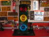
What you see above are, from left-to-right, phases 1-4, the overlap board, and phases 5-8.
I'm using 1.2K/1W resistors to protect the LEDs. The basic premise is that the A/B/C harness wires will land on these (every last wire save the AC hot/neutral and chassis ground wires). The panels will tie in on the forward pins, and the rear sockets will allow me to jumper onto the I/O board that will exit the bottom of the enclosure to the OPTO22 box (not installed yet). Should make changing around load switches a breeze!


This promises to be an all-winter project. Slow going, but if it's worth doing, it's worth doing right I say!

 I don't know what this does but I want it.
  All these switches intrigue me.


 You are looking at the back side of the ring 2 control panel. Each blue box is a toggle switch. Phase 8 is on the left and is wired to the I/O board, followed by 7 to the right of it. Phases 6 and 5 have yet to be done. To the right of that are 2 groups of switches.... the top group being ring 2 control, and the bottom group being all the misc. I/O not tied to a ring (external start, CNA1/2, test A/B, etc.)
 . That is way beyond my brains' capabilities.....just like about everything else.


 )
)

